Sulfur and Nitrogen Oxides pollution abatement is continuing to be as critical as ever in the context of tighter environmental emission norms and increasing concerns of global warming. The Process chemistry and unit operations associated with SOX and NOX removal techniques are standard and mature. One of the major challenges associated with the technologies is the selection of appropriate materials of construction that provide the lowest total cost of ownership and a high level of corrosion resistance. The advent of newer materials and fabrication techniques have increased the material options available. This paper takes a closer look at one of the options, polyethylene (PE) lined steel pipes manufactured by roto-lining process. This material, though not a recent invention, is relatively new to the field of SOX / NOX Scrubbing systems and is a strong contender among the available options.
SOx and NOx abatement applications are encountered in Coal and Oil-fired Power Plants, Steam Boilers and Marine Engines. Though all these applications have several common features, this paper will focus on marine applications, particularly Scrubbers installed in Ships.
A typical open loop scrubber used for installation in Ships is shown on Fig. 1. The simplest scrubber system available is the open loop scrubber, where water is sourced from the surrounding sea, pumped through a filter and sprayed into the scrubber using nozzles that disperse water into droplets. An open loop scrubber is efficient only if the source of water is alkaline. This can either be done by adding an alkali chemical or by utilizing seawater, which has a natural alkalinity derived from the bicarbonate ion (HCO3– ) present in the seawater.
The hot exhaust gas from a Ship’s engine is led to the inlet at the bottom of a cylindrical packed scrubber to encounter a counter-current flow of aerated sea water sprayed from top of the tower, wherein the SOx and NOx in the exhaust gas is absorbed by the sea water and oxidized by Oxygen in the aerated sea water to Sulfuric acid.
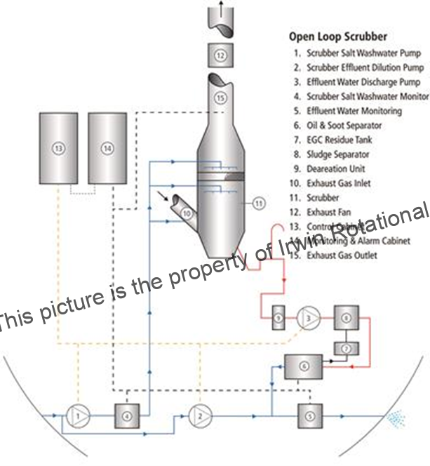
Courtesy: Wärtsilä Corporation
Fig 1. Schematic of a typical Open Loop SOx / NOx Scrubber system in a Ship
The water is discharged back into the sea after particulate matters are removed. The type of solid waste generated from scrubbing is classified as hazardous waste, and therefore stored and later disposed to land based disposal facilities. Closed loop scrubber systems are developed for no-discharge zones, this requires that the scrubber system works on a recirculated flow that is later discharged as the vessel leaves a no-discharge area. Depending on the amount of water consumed and the size of the buffer tank, the closed loop system can only run for a certain amount of time until the liquid is saturated. Therefore, to avoid saturation and increase the time span, the liquid phase is continuously bled off, adding more seawater into the system.
Scrubber system – Chemistry and Corrosive conditions
SOx are formed by a Ship’s Engines during the combustion process due to the oxidation of naturally occurring sulphur in the fuel. In the exhaust gas, the major part of SOx is present as SO2, and a minor portion is SO3.
Gaseous SO2 dissolves in seawater and subsequently is ionized, generating bisulphite and sulphite ions.
Simplified chemistry of the open-loop scrubbing process:
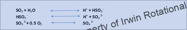
The generated hydrogen ions, are neutralized by the alkalinity of seawater (mainly due to its bicarbonate content), thereby consuming alkalinity. Reactions involving SO3 :
Gaseous SO3 dissolves in water, forming sulphuric acid, which dissociates to sulphate.
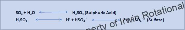
The generated hydrogen ions are neutralized by the alkalinity of seawater (mainly due to its bicarbonate content), thereby consuming alkalinity. (1)
In regions, where alkalinity of Seawater is not adequate and where no effluent discharge is permitted, a closed loop scrubbing process with normal water and external alkali dosing can be employed. The Arctic, Northwest Pacific and Norwegian ocean are some of the areas where alkalinity of Seawater is inadequate for open loop scrubbing. In the interest of brevity, a detailed description of the closed loop process is not included in this paper. The corrosive conditions encountered in the open loop process is more aggressive than that in the open loop process since sea water is more corrosive than normal water and hence the open loop process covered in this paper may be considered as a worst-case scenario.
The surface pH of Seawater usually ranges from 8.1 to 8.9. During scrubbing, the hydrogen ions generated are neutralized by the alkalinity of the Seawater resulting in a pH of 4 to 5. The corresponding concentration of Sulphuric acid can be read off the chart in Fig. 2 which gives the Sulphuric acid concentration against corresponding pH values.
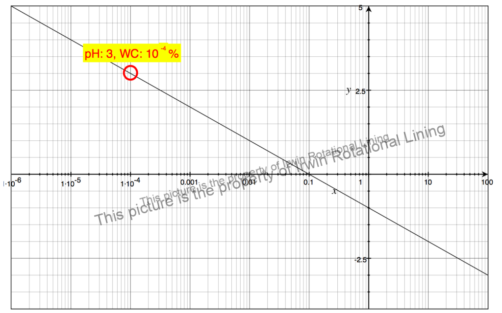 Fig 2. Sulphuric Acid Concentration vs Solution pH (2)
The absorption of NOx gases into the liquid phase is more complex than the absorption of SO2. Not only is the gas-phase NOx in equilibrium with the liquid phase, but equilibrium and kinetic reactions also occur in the gas-phase. This complicates the absorption chemistry of NOx, since different nitrogenous compounds are formed in the gas phase. These compounds can also be dissolved into the liquid phase and lead to different possible reactions that occur in the liquid phase. NOx, in the form of NO or NO2, can be absorbed into the liquid phase.

NO2 has a high solubility, and is easily dissolved compared to NO, which makes it more suited in absorption processes where a high degree of absorption of NOx is wanted.
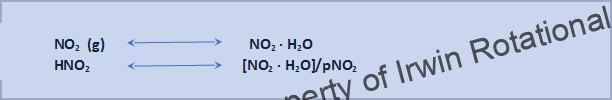
NO2 in liquid phase, can react with water to form nitrous acid (HNO2) and nitric acid (HNO3). Furthermore, these acids deprotonate in an equilibrium reaction.
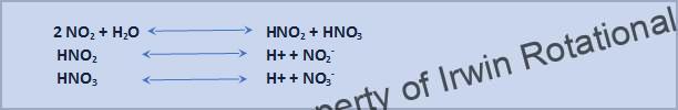
HNO2, as well as HNO3, can also be formed in the gas phase and dissolve into the liquid phase. Nitrous acid has the possibility of forming NO, NO2 in an equilibrium reaction. This reaction is less likely to occur in an environment where pH is equal to or more than 5 (1). Since the solubility of NO is relatively low, the component is likely to return to gas phase.
Presently Ship Vent Gas Scrubbing systems are designed mostly for SOx removal only. However,
Technologies such as the CSNOX Wet Scrubbing Technology developed by Ecospec, Singapore for removing SOx, CO2 and NOx in a single wet scrubber will put Ships using such technologies at a distinct advantage in future when Marine emission regulations may be extended to NOX emissions as well.
Selection of Materials of Construction
From the preceding description of the chemistry involved in the scrubbing process, it should be clear that the materials of the various components of the scrubber system should be suitable for the respective media and temperature indicated in the Table 1 below.
Table 1 Material of Construction Options for SOx and NOx Scrubbers
|
SL.No. |
Location / Part of Scrubber |
Operating Temperature C |
Media |
Material Options |
|
1 |
Inlet Venturi and Inlet Nozzle |
260 to 300 |
Exhaust Gas |
Duplex Stainless Steel (Duplex SS)/Titanium |
|
2 |
Scrubber Body |
50 to 80 |
Seawater of pH range 4 (Inlet) to 8 (Outlet) |
Duplex SS/ Titanium/Polyvinylidene Fluoride(PVDF)/PFA lined Steel Ɨ |
|
3 |
Scrubber liquid Effluent Piping |
40 to 50 |
Seawater of pH 4 to 5 |
Duplex SS/Titanium/PE lined Steel / VE-FRP** |
|
4 |
Scrubber Pump |
20 to 50 |
Seawater of 8 to 9 pH |
Duplex/Titanium/PE lined Steel |
|
5 |
Effluent Tank, Sludge removal system, Effluent Pump & Piping |
40 to 50 |
Seawater of pH 4 to 5 |
Duplex SS/Titanium/PE lined Steel / VE-FRP** |
|
6 |
Exhaust Gas Blower & Duct |
40 to 50 |
Exhaust gas & traces of Seawater of 8 to 9 pH |
Duplex SS/Titanium/PE lined Steel / VE-FRP** |
Ɨ Non-metallic Materials like PVDF/PFA lined Steel are potential options that have superior Corrosion resistance and Temperature resistance as compared to PE and PP lined Steel and may be potential substitutes for Duplex SS.
**Vinyl Ester FRP
Early Ship Scrubbing systems were based mostly on expensive Titanium and Duplex Stainless-Steel alloys. With increasing emphasis on lowering Total cost of ownership (TCO), Options like Viny Ester FRP (VE-FRP) evolved, but these options have a few disadvantages like lower impact strength and reactivity of the resin with the reinforcing glass layer with aging leading to stress cracking.
As pointed out under serial no.2 in Table 1, PVDF/PFA lined steel are cost effective options that can be explored for Scrubber body construction, since these materials have superior corrosion and temperature resistance compared to PE and VE FRP but are significantly cheaper than Duplex SS and Titanium.
More recently, options like PE lined steel piping have evolved offering better impact strength and crack resistance compared to VE FRP and the main goal of this paper is to review the advantages offered by PE lined Equipment and Piping as compared to the existing material options for SOx / NOx Scrubbers. In the context of SOx / NOx Scrubbers, PE lined equipment refers to the lining formed by rotational lining technology only and not other type soft lining like loose liners formed by extrusion lining etc.,
PE Lining by Rotational Lining
The rotational lining is a process of lining the inside of pipes or other SOx components with a seamless, one-piece inner layer of PE plastic. In this lining technique the lined spool is produced by heating and rotating a carbon steel spool with a polymer, which is in a granular/powder form, placed inside the pipe spool. The polymer melts and forms a seamless and uniform liner on the internal surface of the carbon steel pipe. The engineered polymers used for the rotational lining process include additives which increase the bond and adhesion with the prepared metal substrate.
The choice of which polymer to use is based on the chemical resistance properties that are required for the final product. Polyethylene, polypropylene, PVDF or number of other polymers is used for roto-lining. However, polyethylene is the workhorse of the segment and accounts for over 80% of roto-lining applications. The lining thickness varies from 2 mm to 8 mm. The heavy lining thickness allows post machining of critical surfaces that would not be possible with a thinner lining applied by other methods. Virtually any type of metal weldment or casting may be roto-lined. Typical items that may be roto-lined are tanks, carbon steel pipes, fittings, and complex welded structures.
Advantages of rotational lining (3):
Rotational lining offers significant advantages when compared with other lining techniques or thermoforming:
• Costs for lining and tooling are relatively low
• The roto-lining technique is easily adapted to short production runs, particularly when sets of multiple-cavity molds are used
• Hollow, totally enclosed items as well as pieces with openings can be made
• Rotational lining eliminates the need for secondary tooling
• There is little or no waste due to resin scrap
• Wall thickness and piece weight can be easily controlled
• Rotational lining procedures ensure uniform wall thickness
• Deviations can be controlled to within a tolerance of ±10 percent;
• Pieces with intricate contours and undercuts can be easily molded
• Virtually any size piece can be rotationally molded
• There is a minimum of cross-sectional deformation and warpage
• Rotational lining yields pieces with excellent surface detail and finish
• Rotationally lined items are virtually stress free
• Identical or similar items or different sections on one piece can be molded at the same time in different colors on a single spindle
• Plastic or metal inserts can often be lined as integral parts of the item
• Double wall constructions are feasible.
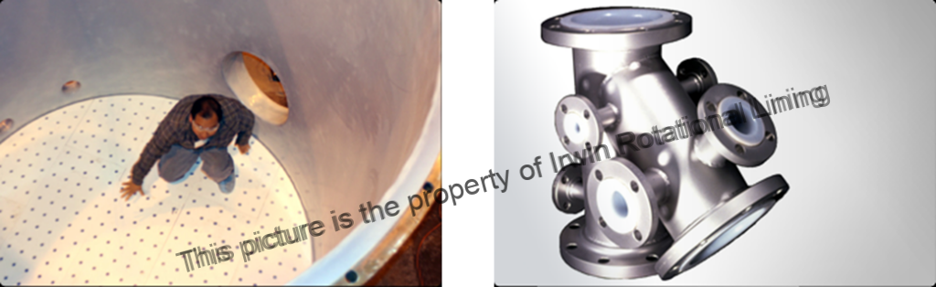 Photo Courtesy: RMB Products Inc. Photo Courtesy: Irwin Rotational Lining
Fig 3. Roto-lined Tanks > 10 Ft diameter.
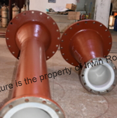
Photo Courtesy: Irwin Rotational Lining Photo Courtesy: Irwin Rotational Lining
Fig 4. Venturi Type Pipe Fittings
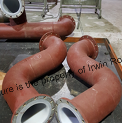
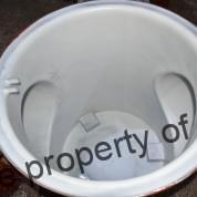
Photo Courtesy: Irwin Rotational Lining Photo Courtesy: Irwin Rotational Lining
Fig 4. Roto-lined S-Shaped Pipe Bends. Fig. 5. Roto-lined Pipe Fitting Internal View
Rotational lining is a mature technology that has been proven in various harsh chemical applications. Fig. 3 to 5 demonstrate the diverse capabilities and applications of Roto-lined equipment, pipes and pipe fittings ranging from large tanks to complex shaped piping.
In addition to the range of sizes and intricate geometries that the roto-lining technology can cater to, material options within Polyethylene like Low Density Polyethylene (LDPE), Linear Low Density Polyethylene (LLDPE) or Linear Medium Density Polyethylene (LMDPE),High Density Polyethylene (HDPE) and Cross-linkable Polyethylene (XLDPE or XLPE) are available which broadens the application range of PE lined equipment and piping beyond what was possible earlier.
PE lining Material options
Materials like LLDPE, LMDPE and HDPE are suitable only for applications which are not very harsh like dilute acid (less than 50% by weight Sulphuric acid) and alkali solutions at temperatures in the range of 20 to 50 C. The Sulphuric acid conc. encountered in a Scrubber is only of the order of less than 1% by weight, though LLDPE, LMDPE and HDPE are suitable for Scrubber piping applications, XLPE is a more robust and cost-effective material for these applications considering its superior Temperature resistance, Impact strength and resistance to stress cracking. A research for a Polyethylene with a higher temperature resistance closer to Thermoset plastics led to the discovery of XLPE, a cross-linked Polyethylene.
Cross-Linked Polyethylene (XLPE) – It is a form of polyethylene with cross-links. In
this case, the molecules arrange themselves in a specific pattern relative to each other, with an
actual chemical bond being formed between the individual molecules. This, in effect, locks the
molecules into a semi-rigid three-dimensional shape. Heating these materials does not weaken
the bonds between the molecules. As a result, the cross-linked materials retain their physical
properties at elevated temperatures. The primary advantages achieved through cross-linking are improved creep, low temperature impact strength, heat and improved resistance to Stress cracking, with a reduction in permeation (4). These attributes allow XLPE to be used in demanding applications such as fuel and chemical tanks.
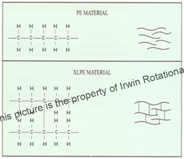 Fig. 6 Molecular structures of Linear and Cross-linked Polyethylene
The following factors of XLPE below makes it a robust material of construction for SOx / NOx Scrubbers.
- Elevated Temperature Capability (up to 70 C)
- Higher resistance to oxidative media like Sulphuric acid and sodium hypochlorite encountered in ballast water treatment system
- Excellent Stress corrosion cracking resistance
- Excellent Impact Strength
On account of these factors, PE has a clear edge over competing materials like VE-FRP as summarized in Table 2. Metallic MOC options like Duplex Stainless Steel and Titanium are excluded from this comparison since these metallic options are much more expensive than PE lined Steel and VE-FRP.
Table 2 Comparative Features of XLPE Lined Steel and VE-FRP
|
Sl.No. |
PE Lined Steel |
VE-FRP |
|
1 |
Higher Chemical Resistance. Single material homogenous layer. No dual material in lining eliminating interface corrosion. |
Prone to formation of “Chemical attack” in the interface between resin and glass fiber ƗƗ. |
|
2 |
Excellent Impact resistance. Better resistance to vibration failure. Particularly, Ship Scrubbers are prone to vibrational forces. |
Impact resistance inferior compared to XLPE. Susceptible to damage during installation and poor resistance to vibrational failure. |
|
3 |
Design Flexibility for equipment & parts with complex shapes |
Limited flexibility. Not suitable for intricate and complex shapes. |
|
4 |
Being a lining bonded to steel, XLPE lined steel offers a safer option in the event of a fire, as steel backing will continue to contain the process media. |
Immediate failure in the event of a fire. Fumes generated by combustion of VE-FRP are much more toxic than fumes generated by Polyethylene combustion. |
|
5 |
Environmental Friendly. Polyethylene is non-toxic and benign compared to VE-FRP |
Most VE-FRP have Bisphenol-A in them and Bisphenol-A is a toxic chemical that is increasingly facing ban worldwide. |
|
6 |
Conforms to Classification Society requirements for Water-tight bulkhead penetrations. |
Classification Society requirements do not permit use of FRP pipes in areas where Scrubber piping is installed in Ships. |
ƗƗ -A reduction in the mechanical properties by water / chemical absorption has been attributed to the debonding of the fiber–matrix interface, which leads to delamination and cracking combined with plasticizing of the matrix (5)
Based on the above comparative evaluation, a suggestion of PE lined materials for the various parts of a SOx / NOx scrubber system is shown in Fig.6
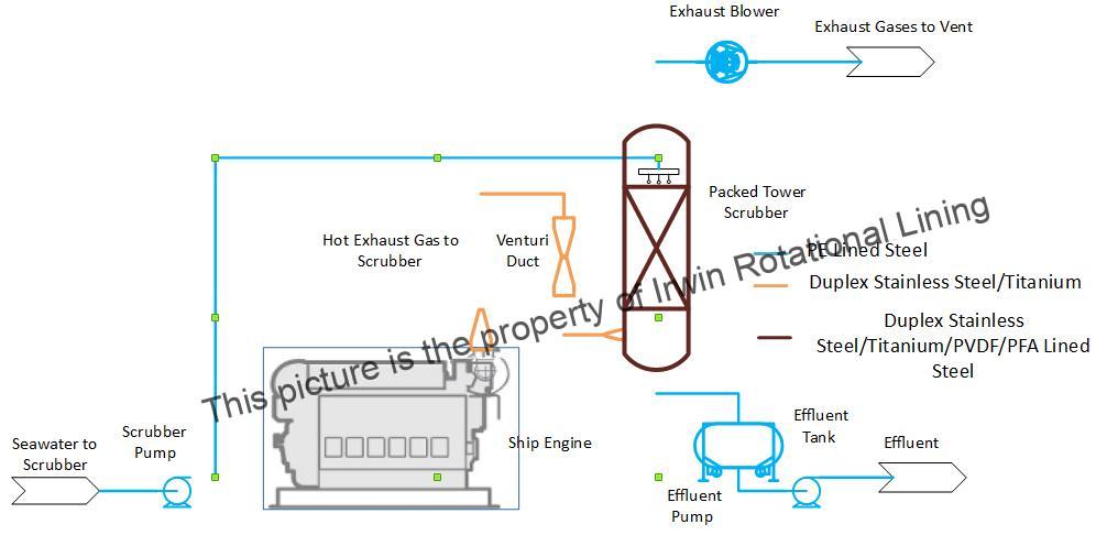 Fig 6. Suggested PE Lined Material Options for a SOx / NOx Scrubber system
Conclusion
PE roto-lined equipment and piping offer a robust and cost-effective solution to the problem of selection of materials for SOx / NOx scrubber systems. It is worthwhile to make a detailed evaluation of this option before making a final choice of materials for scrubber systems as they have several technical advantages over competing materials and could also potentially provide lowest cost in terms of Total cost of Ownership.
References
- Andersson, K. Brynolf, S., Lindgren, F., Wilewska-Bien, M. Shipping and the
- Environment. Springer Nature, Gothenburg, 2016.
- STI Technical Note for Calculating Sulphuric Acid Concentration, STI-TN-20170818-1
- A Guide to Rotational Molding 5717; Lyondell Basell.
- Abell, Dixon Harold, “A Study of the Cause of Failure of Rotationally Molded, High-Density Polyethylene, Sodium Hypochlorite Storage Tanks” (2011). All Theses and Dissertations. 260912
- J. Yao, G. Ziegmann, “Water Absorption Behavior and Its Influence on Properties of GRP Pipe” Journal of Composite Materials, Vol. 41, No. 8/2007.


